Prescript 1
중요한 점을 빼먹었다.
네트워크 이중화 (본딩)처럼 간단하게 전선 두개 엮는다고
로드밸런싱이 되는 것은 아니다.
완벽하게 칼전압을 맞추는 전원공급장치와
이상적인 다이오드, 모든 수치가 0.00001피코암페어/볼트의 오차도 없는 녀석이면 로드밸런싱이 된다.
여기서 로드밸런싱이란;
9V 2A를 빨아먹는 장치 2개가 있고
9V 3A를 출력하는 어댑터 2개가 있다고 치자.
어댑터 용량 합은 6A로, 전체 최대 소모전류 4A를 넘지만
각 어댑터별로 2A씩만 정확히 당겨간다는 것은 보장이 아니된다.
전압의 경우 두 어댑터의 전압이 대부분 다르므로
(동일한 제품 2개를 동시에 사도 미세하게 다르다)
전압이 높은쪽부터 당겨오기 시작한다.
어댑터 1은 9.6V를, 어댑터 2는 9.3V를 출력한다고 할 때
어댑터 1에서 4A를 당겨오려고 시도할 것이다.
왜? 다이오드로 엮었기 때문에, 전압이 높은 놈에게 둘 다 붙은 형태로 작동하기 때문.
그럼 9.6V를 내보내는 어댑터1은 자기 용량을 초과하므로 전압이 점점 떨어지기 시작한다.
그러다가 9.3 - 0.2볼트(다이오드 순방향 강하), 9.1볼트까지 전압이 떨어지면 그 때부터 두 번째 어댑터에서 전류가 나가기 시작한다.
그럼
9.6볼트짜리 어댑터 3A
9.3볼트짜리 어댑터 1A
형태로 죽지못해 살아있는 로드밸런싱이 되고,
허용 초과전류가 간당간당하게 걸리는 어댑터 1은 조만간 사망하게 된다.
그럼 2암페어짜리 어댑터로 4암페어 로드를 감당해야함
로 장비가 죽든지 어댑터가 같이 터지든지 하게 된다.
직류 어댑터는 병렬로 연결할경우
- 로드밸런싱이 되는 회로를 구현하거나 (복잡함)
- 어댑터 하나로 모든 장비를 카바칠 수 있는 용량을 구비하거나
- 이중화로 오히려 수명짧아짐을 감내하거나
세 가지 옵션이 있다.
나는 2-3번을 택한 케이스이다.
지인이 내 글을 보고 질문을 주었다.
”컴퓨터 메인보드 전원 이중화를 값싸게 하고싶은데,
메인보드 파워레일 브레이크아웃 보드를 사다가 그냥 아래처럼 다이오드로 이으면 되는거 맞냐“
ㅋㅋㅋㅋ큰일난다잉.
보드에 이중화가 구현되어있지 않으면
(주로 E5 서버보드 중 특수목적보드, 어바야 Avaya 네트워크 장비같은 애들)
값싸게 할 수 있는 방법은 없다.
...
2010's 초반에 지어진 나의 서울 사육장은
10년대 초반의 '보편적'인 통신시스템에 기반하여 배선이 되었다.
지어진지 10년이 넘은 이 집을 구매하고나서
기존의 Coaxial 케이블과 Cat5 이더넷을 모두 걷어냈다.
Cat6 케이블 4개면 꽉 차는 주름관으로 인해
각 튜브별로 Cat6라인을 3개씩 우겨넣었다.
(튜브 하나는 안내선, 즌문용어로 요비선, 이 안 들어갔다.
제거할 때 기존 케이블에 묶어뒀던 요비선이 빠져버렸고,
일단 제거한 뒤 요비선을 다시 쑤셔박아도 안 들어갔다. 30분동안 요비선 2개를 가지고 씨름하다가 포기.)
Cat5도 기가빗 이더넷은 잘 되지만
주름관에 덜렁 하나 들어있는 Cat5선...에
Cat 6를 추가하는건 불가능 했기에 제거하고 삽입하였다.
통신함에는
동축 스플리터 1개와
100메가빗 허브 1개만 덜렁 있었다.
(전화선 스플리터는 허브에 구현되어있음)
이에 공유기와 기가빗 허브를 우겨넣었다. 욱여? 우겨? 우겨가 맞는 것 같다.

어댑터는 둘 다 ipTime의 9V 어댑터를 달았다.
(공유기/스위칭 허브와 딸려온 어댑터가 뭔지 모르겠어서 전압 맞는 것을 그냥 썼다.)
문제는 ipTime의 고질병,
어댑터의 짧은 수명때문에
고민이 되었다.

전에 노트북 충전기 (19V) 2개를 병렬로 연결해서 쓴 적이 있다.
게이밍 노트북 정격 전류가 5A정도 되었는데
기존의 충전기가 고장나버리는 바람에
가지고 있는 스페어 충전기들을 뒤져보았다.
전압이 맞는 어댑터는 3A 뿐.
이에 커넥터를 참수형 시키고
병렬로 연결해 커넥터를 다시 연결했다.
그 노트북은 아직도 현역으로 있다.
(전원은 안 켠지 1년이 넘었다 ㅋㅋ)
이때 배운 지식이 기억나서
짤막한 로그를 남겨보려 한다.

사용한 공구 / 부품
- 항공가위
- 크림플러 (오메가형, 페럴용 등등)
- 크림플 커플러
- 수축튜브 (크림플, 납땜, 일반...)
- 스페어 전선 (PC 파워서플라이에서 잘라낸 전선)
- 와이어 룸 (Wire loom)
- 쇼트키 다이오드 (가장 중요한 부품)
- 만능기판
- DC 커넥터 (암/수)
- 인두기
- 납땜용 납 (나의 경우 SMD용 솔더 페이스트 + 일반 땜납)
...
쇼트키 다이오드가 없어도 작동은 하지만
안전상의 문제가 있다.
A, B 어댑터 중 A가 고장났다고 가정해보자.
- B 어댑터의 전류가 A로 (역방향) 유입되거나,
- A 어댑터의 열화로 전압이 떨어질 경우
두 어댑터의 전압차로 (V_A > V_B) A 어댑터에 전류가 (역방향) 발생할 수 있다.
단순한 다이오드 브릿지 + 커패시터 형태의 어댑터라면
문제가 없...으려나? 모르겠네.

여튼 요즘 어댑터는 보호회로가 추가되기 때문에
역방향 전류가 어떤 문제를 일으킬지 모른다.
가장 걱정되는건 심한 발열 (or 발열의 누적 등)
스파크 발생 + 인화성 가스의 만남으로
화재가 나는 것이다.
이상전압 / 전류 발생으로 장비 고장이야 뭐..
네트워크 장비는 소모품이기 때문에 그러려니 하지만.
여튼.
다이오드의 역방향 전류 차단 성질을 이용해서
이러한 문제를 제거하는 안전장치를 추가해야된다.
일반 다이오드는 0.6~0.7V의 순방향 전압강하가 발생한다.

반대로 역전압이 걸리게 되면
전류가 흐르지 않는다.

아, 물론 항복전압을 넘기게 되면 역전류가 통과하게 되고
(이걸 활용한게 제너다이오드이다)
항복전압 미만에서도 역방향 미세전류가 흐른다.

순방향의 전압강하를 낮추고
일반 PN접합 다이오드의 문제 (제한적인 순방향 전류 허용)를 해결한 다이오드,
쇼트키 다이오드를 사용하면 된다.
(기존의 P도핑 + N도핑 (반도체 + 반도체)에서 반도체 + 금속 접합으로 전류량을 높였지만
역전압이 30 ~ 100V정도로 매우 낮고 역전류 누설이 크다)
회로이론(2학년 과목)이랑 마이크로전자회로 (3학년 과목)에서 안 배웠다.
MOSFET정도만 배운듯.
DC 어댑터 병렬구성할 때 인터넷을 통해 배운게 쇼트키.

기호는 이렇게 생겼다.
짧은 열쇠 쇼트 + 키 가 아니고
Schottky
발터(Walter) 쇼트키 (독일사람이다)
나는 1N5819 다이오드
(40V 1A)를 사용했다.
집에 있는 것 중 적당한게 이것뿐.


순방향 전압강하가 0.212V, 0.215V이다.
현재 사용중인 어댑터 2개의
오픈 서킷 (로드가 걸리지 않는 상태) 전압이 각각
- 9.23V
- 8.88V
로 잡힌다.
일단 어댑터부터 만들자.

이렇게 2 in 2 out 커넥터를 만들 예정이다.
회로는 아래와 같다:

-는 입출력단 4개가 모두 연결되어있다.

DC 입력 하나가 고장날 경우
DC 출력 둘 다 전원이 공급되지만
고장난쪽 입력단으로 전류가 흐르지 않는다.

만능기판은 책상에 올려놓고
절단할 라인을 책상 끝에 맞춘 뒤
탁!하고 주먹(이나 핸드폰이나 렌치나 드라이버나 등등)으로 내려치면
깔끔하게 부러진다.
항공가위의 절삭력이 끝내준다.
항공가위로 다듬고 나서 다이오드와 전선을 끼웠다.


쇼트키 다이오드의 방향은
' 검은색 바디 -> 은색 띠가 있는 방향 ' 이
순방향 전류의 방향이다.
사진상에서
- 왼쪽이 DC 입력단,
- 오른쪽이 DC 출력단
이다.

마땅한 헬핑 핸드가 없어서
솔더 페이스트를 발랐다.
전선을 손가락으로 잡은 상태에서
인두기로 납을 녹이려면 어쩔 수 없었다.

다이오드 끝을 서로 맞닿게 구부려놓았기 때문에
오른쪽 부분을 쇼트시킬 수 있었다.
SMD용 솔더페이스트는 진짜 편하다.
녹는점도 낮고, 페이스트랑 땜납이 같이 있어서 최고임.


트리밍을 하고 나서
-쪽 전선은 단순히 크림플 커플러로 찝었다.
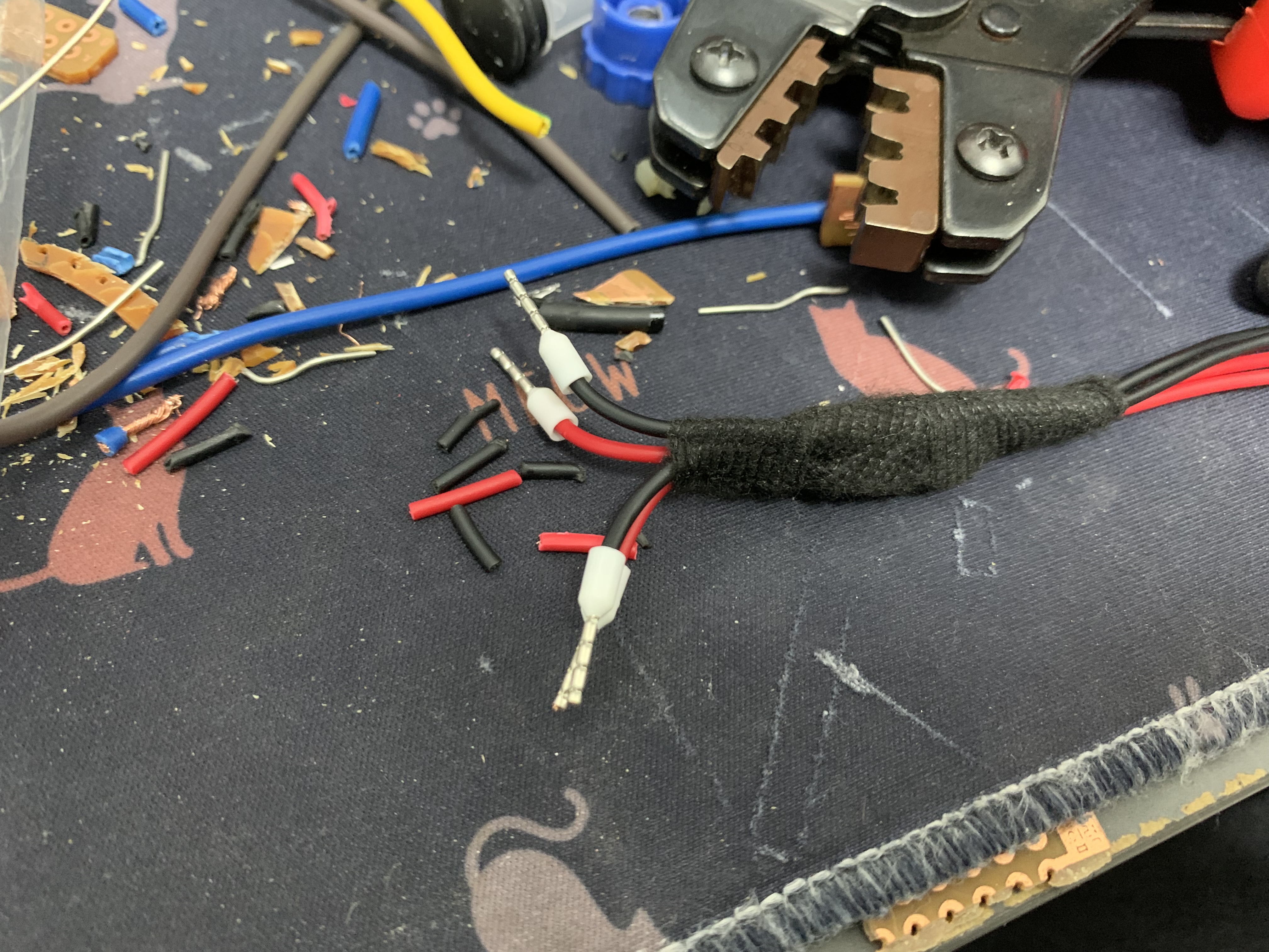
수축튜브 + 절연테이프 + 부직포 테이프로 감싸준 뒤
DC 커넥터쪽 전선은 Ferrule로 감싸줬다.

테스트용 ipTime 공유기,
A1004NS에 물려봤다.
(12V 어댑터 사용)
서로 다른 12V어댑터 2개를 연결했다.
휴.
아무 문제 없이 잘 된다.

입력 2개는 그냥 어댑터 2개를 연결했고
출력 하나는 공유기, 전류측정용 케이블 (자작)을,
나머지 출력은 전압 측정용으로 멀티메터에 연결했다.


1004NS의 경우
- 부팅시 ~250mA
- idle시 (wifi off, LAN 모두 연결 안함) 150mA
정도 소모한다.
(와이파이 켜면 소비전류가 늘겠지)
전압 강하도 충분히 수용 가능할만 하다고 판단,
현업에 투입했다.
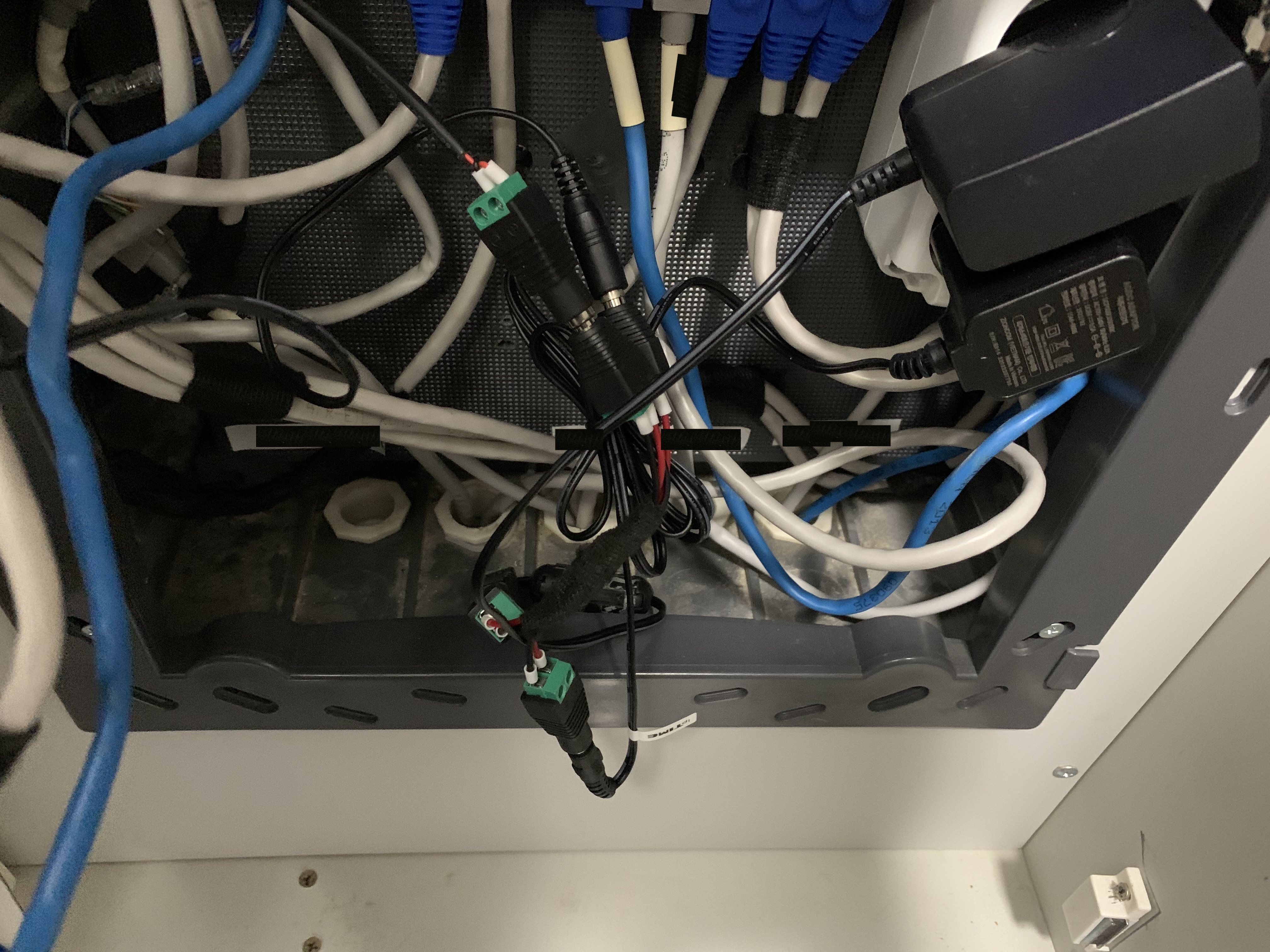
8.88V나오는 어댑터 교체,
어댑터 하나로도 공유기 2대,
트래픽이 좀 있는 부하를 감당한다.
같은 어댑터 2개를 사용하면
- 리던던시 (이중화 백업)
를 보장하지만
- 다이버시티 (같은 취약점 공유)
가 없다.
그래서 일부러 서로 다른 어댑터를 사용했다.
같은 제품을 2개 쓰면
mean time between failure (MTBF, 평균 수명으로 보면 된다)가 같기 때문에
동시에 고장날 확률도 높고,
같은 취약점 (고질병)을 가지기 때문에
같은 문제상황 발생시 (전압 흔들림, 순간단전 등)
동일하게 동시에 고장날 확률이 높기 때문이다.
그래서 서버 구축할때도
하드디스크 여러장 사게 되면
같은 모델 다른 생산주차를 사거나
다른 제조사나 다른 모델 등을 일부러 섞어 쓰는 것으로 알고 있다.
물론 나는 그냥 다나와에서 2개 사긴 하지만.ㅋㅋ
https://thewanderer.tistory.com/97
[토막글] 링크시스 E7350 공유기 (WPA3) Log (Feat. 통신단자함)
노르웨이어를 배우려고 책을 드디어 샀다. 2023.04.05 - [In Progress/Brainstormed but that's it.] - 노르웨이지언을 배워볼까. (탐색중) 노르웨이지언을 배워볼까. (탐색중) 한 10년? 12년? 전에 유툽에서 (당시
thewanderer.tistory.com

링크시스 공유기를 사면서
병렬화를 다시 해제하였다.
(둘 다 12V이긴 하나 소모전력이 꽤 높아서 카바칠 어댑터를 두 개나 별도로 사야된다)
https://thewanderer.tistory.com/94
개인 서버 망분리 고민 log (Feat. NAT & Sniffing) - 작업중
나는 사생활 보호에 극도로 민감한 편이다. 게다가 I 성향이 매우 강해서.. 다른 사람들이랑 어울리는걸 별로 안 좋아한다. 한국의 집단주의적인 문화때문에 여행지 가서 '한국인이다' 하며 반기
thewanderer.tistory.com
허브도 넷기어 제품으로 (IP 할당받고, 웹 UI 띄울 수 있는 놈으로) 교체했다.
MAC addr flood 공격이 들어오면
싸구려 ipTime 허브는 (칩셋 사다가 PCB랑 껍데기만 만들어 파는 제품이다보니)
어김없이 정신을 잃고 더미허브 모드로 작동한다.
(모든 포트에 들어온 패킷을 다 뿌려버림)
물론 내부에 침투해서 맥 어드레스를 수천개씩 뿌릴 정도면 이미 심각한 상황이긴 하나..
혹시 들어와도 스니핑 못하게끔..ㅋㅋ
근데 managed L3도 맥주소 플러딩을 하면 동일하게 더미허브모드로 페일세이프가 되는 것 같다.
일단은 Vlan때문에 산거니깐.
조만간 220AC - 5V, 12V 출력을 내는 파워 어댑터로
(3D 프린터나 소형 CNC같은데 들어가는 큼지막한 걸로)
병렬화를 구성하고
단자함을 교체할 예정이다.
내 집이니까
내 쪼대로 할 수있어서 너무 좋다.
콘센트도 전력절감? 쓸데없는것 다 걷어내고
그냥 2구짜리로 (전력절감? 콘센트는 2구 공간을 차지하고 구녕은 1구만 나온다) 바꿔버렸다.
건축법을 한참 뒤져봤는데 ' 건축할 때 30%를 저전력 뭐시기 블라블라고 설치하여야 한다 ' 만 있고
' 2015년 이후에 건축된 집은 콘센트 30%가 뭐시기 콘센트로 유지하여야한다 ' 는 없었다.
뭐 자동차처럼 정기적으로 검사나오는것도 아니고.. 쌩까고 바꿨다.
여튼.
인터넷엔 단자함 박스를 잘 안팔거니와 (사이즈 맘에 드는건 쓸데없이 비쌈)
평생 살 집도 아니고 언젠가 또 매각할 집인데
돈을 쳐발쳐발해서 의미가 있나 싶은 생각이 자꾸 든다.
(구찮다 이말이다)
일단은 저 석고보드에 멀티탭 끝자락만 다이소에서 사다 박고
어댑터를 주렁주렁 달아서 빈 구멍을 통해 전원선을 밀어넣었다.
이것도 나쁘지는 않은듯...
(어댑터 고장나면 통신함쪽 합판 패널을 쥐어뜯어야하는게 번거롭다)
2023.11.10 - [Life Log/Quirky Perks] - 도어락 상시전원 개조 (니켈수소합금 충전지 + 접점 커넥터)
도어락 상시전원 개조 (니켈수소합금 충전지 + 접점 커넥터)
서울에 자그마한 인간사육장을 구매한지 1년이 넘어간다. 전에도 근 10년을 살던 집이라 (같은건물 같은동 같은층 옆옆옆옆옆옆집) 구조가 아주 익숙하고 이놈의 집은 뭐가 부실한지 뭐가 잘못
thewanderer.tistory.com
전원부 2개 이상을 입력으로 받을 때
쇼트키를 쓰는건 내 빡대가리에서 나온
방구석 엔지니어의 뇌피셜 테크닉이 아니다.
(디스클레임이 하나 들어왔다)
삼성 도어락에 건전지가 8개 들어가는데
(4개씩 2개조)
기판에 쇼트키가 납땜되어있다.
아니라고! ㅜ
어!!
13th Septembre 2024
피티형 데리고 컨설팅을 좀 받아봤다.
필자
Yes, using diodes for redundancy is a common approach, but as you’ve noted, it has some limitations, particularly with the voltage drop and the fact that only one source provides power at a time. Here are some alternative approaches to achieve redundant power sources that can handle small differences in voltage and provide more balanced power:
- Ideal Diode Controllers: These are specialized ICs designed to act as diodes but with much lower forward voltage drops and better performance. They use MOSFETs to reduce the voltage drop compared to traditional diodes. Some popular ICs are the LTC4355 from Analog Devices and the MAX40080 from Maxim Integrated. Ideal diodes allow for more efficient power switching and better performance in redundancy applications.
- OR-ing Diodes with Higher Precision: If you still prefer diodes, using Schottky diodes instead of standard silicon diodes can reduce the forward voltage drop. Schottky diodes have lower forward voltage drops, which can improve efficiency and reduce the amount of power lost due to the diode’s forward voltage.
- Active OR-ing Circuits: Active OR-ing circuits use MOSFETs or dedicated OR-ing controllers to combine multiple power sources. These circuits have better efficiency and can handle small differences in voltage more effectively. The MOSFETs used in these circuits can have very low on-resistance, which minimizes voltage drops and power loss.
- Power Mux ICs: Power multiplexers (Mux ICs) are designed to select between multiple power sources based on certain criteria. These ICs can automatically switch between power sources, providing seamless failover and better control. Examples include the MAX14920 from Maxim Integrated and the TPS2115A from Texas Instruments.
- DC-DC Converters: Using DC-DC converters with adjustable output voltage can help balance the power sources. You can adjust the output of one or both converters to ensure they are closely matched, reducing the risk of one source providing most of the current.
- Load Sharing Controllers: For more advanced applications, load-sharing controllers can be used to balance the load between multiple power sources. These controllers are designed to ensure that each power source shares the load proportionally, which helps in situations where sources have slightly different voltages or current capabilities.
- Power Management ICs: Some power management ICs are designed specifically for redundancy and power source management. These ICs can provide advanced features like fault detection, automatic switching, and load balancing.
When designing a redundant power system, it's essential to consider factors such as the current ratings of the components, thermal management, and overall system efficiency. Each method has its advantages and trade-offs, so selecting the right approach depends on the specific requirements of your application.
필자
elaborate on power management ICs
지피티
Power management ICs (PMICs) are specialized integrated circuits designed to handle various aspects of power supply management, including voltage regulation, power sequencing, and redundancy. In the context of redundant power systems, PMICs can provide sophisticated features to ensure reliable and efficient power distribution. Here’s a detailed look at PMICs and how they can be used for redundant power applications:
Key Functions of PMICs
- Voltage Regulation: PMICs often include multiple voltage regulators to provide different voltage levels required by various components in a system. They can include buck converters (step-down), boost converters (step-up), and LDOs (low-dropout regulators).
- Power Sequencing: PMICs manage the order in which different power rails are turned on or off. This is critical for systems with multiple power domains where specific sequencing is required to ensure proper startup and shutdown.
- Power Redundancy and OR-ing: For redundant power applications, PMICs can integrate OR-ing circuits that allow multiple power sources to be connected to a load while ensuring that the source with the higher voltage supplies power. This is often achieved using MOSFETs to minimize voltage drops.
- Load Sharing: Advanced PMICs can manage load sharing between multiple power sources or batteries. This ensures that no single source is overloaded and helps balance the load to improve overall system reliability and efficiency.
- Fault Detection and Management: PMICs can detect faults in the power sources or in the power distribution network and take corrective actions. This includes features like over-voltage protection (OVP), over-current protection (OCP), under-voltage lockout (UVLO), and thermal shutdown.
- Battery Management: In battery-powered systems, PMICs handle battery charging, monitoring, and protection. They can manage charging profiles, battery health, and safety features to extend battery life and ensure safe operation.
- Power Path Management: PMICs can manage the power path between the input sources and the load, including seamlessly switching between different power sources or batteries based on availability and power requirements.
Examples of PMICs for Redundant Power Applications
- Texas Instruments TPS2115A: This IC is a power multiplexer that automatically selects between two input power sources. It is designed for applications requiring redundant power supplies, providing seamless switching and protection.
- Maxim Integrated MAX14920: This power multiplexer IC is designed for high-current applications and offers features like automatic power source selection and load sharing. It can be used to manage multiple power sources and ensure continuous power availability.
- Analog Devices LTC4412: This IC is an ideal diode OR-ing controller that provides low-loss power source selection. It uses MOSFETs to minimize voltage drop and improve efficiency in redundant power systems.
- Linear Technology (now part of Analog Devices) LTC4410: This is another ideal diode controller that ensures efficient OR-ing of power sources with low voltage drop and high reliability.
Considerations When Choosing PMICs
- Current Rating: Ensure the PMIC can handle the maximum current required by your application.
- Voltage Range: Verify that the PMIC supports the input and output voltage ranges needed for your power sources and load.
- Thermal Management: Assess the thermal performance and cooling requirements, especially in high-power applications.
- Features: Consider additional features such as fault detection, battery management, and load sharing based on your specific needs.
PMICs can significantly simplify the design of power systems by integrating multiple functions into a single package, improving reliability, and optimizing power management.
dayum.
피티 데리고 나중에 고민좀 해봐야겠다.
필자
elaborate on active or-ing
지피티
Active OR-ing is a technique used in power management to connect multiple power sources to a single load while ensuring efficient and reliable operation. Unlike passive OR-ing, which uses diodes to connect power sources, active OR-ing utilizes active components, typically MOSFETs or specialized ICs, to achieve better performance. Here’s a detailed explanation:
Key Concepts of Active OR-ing
- Principle of Operation:
- Active Components: Active OR-ing circuits use transistors (usually MOSFETs) to manage the connection between power sources and the load. Unlike passive diodes, which always have a forward voltage drop, MOSFETs can be turned on with very low resistance when they are conducting, reducing power loss.
- Low On-Resistance: MOSFETs used in active OR-ing have very low on-resistance (Rds(on)), which minimizes the voltage drop across the switch and improves efficiency.
- Benefits of Active OR-ing:
- Reduced Power Loss: Since MOSFETs have a much lower voltage drop compared to diodes, active OR-ing circuits can significantly reduce power loss and improve overall system efficiency.
- Improved Performance: Active OR-ing allows for more precise control over power sources, better handling of small voltage differences, and smoother transitions between power sources.
- Enhanced Reliability: The use of MOSFETs provides more reliable operation with less thermal stress and better performance over a wider range of operating conditions.
- Implementation:
- MOSFET-Based OR-ing: In a typical MOSFET-based OR-ing circuit, MOSFETs are used to connect each power source to the load. The MOSFETs are configured to ensure that only one power source supplies the load at a time, while the others are effectively isolated.
- Control Logic: Some active OR-ing circuits include control logic to manage the switching between power sources. This logic ensures that the power source with the highest voltage is used while isolating lower-voltage sources.
- Applications:
- Redundant Power Systems: Active OR-ing is used in systems requiring redundant power sources, where it’s essential to maintain power availability even if one source fails.
- Battery Management: In battery-powered systems, active OR-ing can manage power from multiple batteries or charging sources, ensuring efficient power transfer and extended battery life.
- Power Supply Modules: Active OR-ing is often used in power supply modules and systems requiring high efficiency and reliability.
Examples of Active OR-ing Circuits
- Ideal Diode Controllers: These are specialized ICs designed to act as ideal diodes using MOSFETs, providing low voltage drops and efficient power management. Examples include:
- LTC4355: An ideal diode controller from Analog Devices.
- MAX40080: A high-efficiency ideal diode from Maxim Integrated (now part of Analog Devices).
- OR-ing Controller ICs: These ICs are designed for specific applications where multiple power sources need to be combined efficiently.
- TPS2115A: A power multiplexer IC from Texas Instruments that manages redundant power sources and provides automatic switching.
Design Considerations
- Current Handling: Ensure that the MOSFETs or ICs used can handle the maximum current required by your application.
- Thermal Management: Proper heat dissipation is crucial, especially if the circuit handles significant power.
- Voltage Ratings: Verify that the components used are rated for the voltages involved in your application.
Active OR-ing is a powerful technique for improving the efficiency and reliability of power management systems by using advanced components to overcome the limitations of passive methods.
흠.
필자
then lets just say, that I've got a couple of 5V 1A power (identical, but slight voltage difference occurs due to the reality) and a load that can pull 5V 1.5A max. If the load pulls 1.5A, will the active or-ing circuit balance the load?
피티
In the scenario where you have two 5V 1A power sources with a slight voltage difference and a load that can pull 5V 1.5A, an active OR-ing circuit will not inherently balance the load between the power sources. Instead, active OR-ing circuits are designed to ensure that one power source supplies the load at a time, while isolating the other sources.
Here’s how it typically works:
Operation of Active OR-ing in Your Scenario
- Power Source Selection:
- Single Source Supply: Active OR-ing circuits are designed to select the power source with the higher voltage to supply the load. In the case where two power sources are connected, the one with the slightly higher voltage will supply the majority of the current.
- Voltage Difference Handling: Active OR-ing circuits use MOSFETs to handle the slight voltage differences efficiently. The MOSFETs will ensure that the power source with the higher voltage is connected to the load, while the lower voltage source is effectively isolated.
- Load Distribution:
- Not Balanced: Active OR-ing circuits typically do not balance the load between multiple power sources. Instead, they ensure that one source provides power while the other is isolated. This is because MOSFETs used in active OR-ing circuits are not designed to share load current in a balanced manner. They only switch on or off based on the voltage levels.
- Redundant Power: The main purpose of active OR-ing in this context is to provide redundancy and protect against power source failure, not to balance the load.
Balancing Load Between Power Sources
To achieve load balancing between multiple power sources, you would need a different approach:
- Load Sharing Controllers: Specialized load-sharing controllers are designed to balance the current between multiple power sources. These controllers manage the distribution of current to ensure that each power source shares the load proportionally.
- Example: An example of a load-sharing controller is the LTC4412 from Analog Devices, which can manage multiple power sources and balance load sharing to some extent.
- Current Sharing Circuits: These circuits use feedback mechanisms to monitor the current from each power source and adjust accordingly to share the load evenly. This often involves using additional circuitry and control logic.
- DC-DC Converters: Using DC-DC converters with current-sharing features can also help distribute the load evenly between multiple power sources. These converters can regulate the voltage and current to ensure balanced power distribution.
Summary
In summary, an active OR-ing circuit will not balance the load between your two 5V 1A power sources. It will ensure that one power source supplies the load while isolating the other. To achieve load balancing, you would need a dedicated load-sharing controller or current-sharing circuit that is specifically designed for that purpose.
필자
Aha, then it is a bit different with OR in digital circuit, am I correct?
피티
Memory updated - has knowledge of digital circuits.
Yes, you’re correct—active OR-ing in power management is quite different from the OR function in digital circuits.
Digital OR Gate
In digital circuits, an OR gate is a basic logic gate that outputs true (high) when at least one of its inputs is true. The behavior of a digital OR gate is straightforward:
- Inputs and Outputs: It has binary inputs and outputs, and the output is determined by the logical OR of the inputs. For example, with inputs A and B, the output YY is A OR BA \text{ OR } B.
- Voltage Levels: It operates purely on digital voltage levels (0V for low, and a positive voltage for high) and does not involve current management.
Active OR-ing in Power Management
In contrast, active OR-ing circuits are used for managing power sources:
- Voltage Handling: These circuits deal with analog voltage levels and involve power management to handle slight voltage differences and current flow.
- Purpose: The primary goal of active OR-ing is to connect multiple power sources to a single load in a way that ensures efficient power delivery and redundancy. The circuit selects the power source with the highest voltage and isolates others to avoid direct current flow through the lower voltage source.
- Components: Active OR-ing uses MOSFETs or specialized ICs, which have different characteristics and functions compared to digital OR gates.
Key Differences
- Function:
- Digital OR Gate: Performs a logical operation on binary signals.
- Active OR-ing Circuit: Manages and optimizes power delivery from multiple sources to a load.
- Components:
- Digital OR Gate: Uses logic gate ICs or discrete transistors.
- Active OR-ing Circuit: Uses MOSFETs or ideal diode controllers for efficient power switching.
- Application:
- Digital OR Gate: Used in digital logic circuits and decision-making processes.
- Active OR-ing Circuit: Used in power management systems for redundancy and efficient power distribution.
In summary, while the concept of "OR-ing" is present in both cases, the implementation and purpose are quite different between digital logic circuits and power management systems.
필자
FYI, I majored 6 and got 5 bachelor's degrees: - BE, Electric and Electronic Engineering - BE, Software Engineering - BE, Information and telecommunication engineering - BE, Information Management and Security (Not really sure it is "engineering" but learned reverse engineering, web and so on) - BA, Linguistics of English You can throw me a hardcore information in computer technology, I can handle em.
피티
Memory updated - has earned five bachelor's degrees: - BE in Electrical and Electronic Engineering - BE in Software Engineering - BE in Information and Telecommunication Engineering - BE in Information Management and Security - BA in Linguistics of English User is comfortable with advanced computer technology information.
That’s an impressive academic background! With your diverse expertise, we can definitely dive into some advanced topics. Whether you’re interested in deep technical details of computer technology, complex systems design, or something else, just let me know what you're curious about!
... 중략 ...
필자
that is great. Here's an idea: - I've got network devices (s.a. L2 & L3 switches and an Router) that can pull up to 12V 1A. - Let's just say there are three devices. - Instead of plugging three independent adapters to each (12V 1.5A power bricks), I can add [an circuit that you suggest] between AC outlets and the devices. - I'd like to power [the circuit] with four 12V 2A, for the redundancy. - Then, [the circuit] redistributes the power to the nw devices. What would be the good choice? I can design an PCB and order, can solder and if MCU is required I can programme.
피티
Memory updated - is interested in designing circuits to manage power distribution for network devices using redundant power supplies. They can design PCBs, order them, and program MCUs if needed.
Your project idea is a great application of power management techniques! Given your requirements and capabilities, here's a detailed approach to designing a power distribution circuit that can handle redundancy and load balancing for your network devices:
Design Considerations
- Power Input and Redundancy:
- Input Power: You have four 12V 2A power sources for redundancy.
- Redundancy Handling: Use an active OR-ing circuit to combine these power sources effectively, ensuring that the load is supplied by the highest voltage source and maintaining redundancy.
- Load Balancing and Distribution:
- Current Requirements: Each device pulls up to 12V 1A, so you need to ensure that your distribution circuit can handle a combined load of up to 3A.
- Output Distribution: Distribute the power to the three network devices, ensuring each receives stable and adequate power.
Suggested Circuit Design
- Active OR-ing with Redundant Inputs:
- Components: Use MOSFETs or specialized OR-ing ICs to combine the four 12V 2A inputs. Ensure that the MOSFETs or ICs are rated for the current and voltage requirements.
- Example IC: The LTC4412 or MAX14920 can be used for high-current OR-ing with redundancy. You might use two of these ICs if you want to combine four sources efficiently.
- Load Sharing and Current Distribution:
- Active Load Sharing: To balance the load among the power sources, you might need a dedicated load-sharing controller or active current-sharing circuit. While not always necessary, this can help ensure that each source contributes proportionally.
- Current Sense Amplifiers: Use op-amps to measure the current from each power source and adjust the distribution if needed. This is more advanced but ensures precise load balancing.
- Protection and Filtering:
- Fuse Protection: Add fuses or circuit breakers to protect against overcurrent and short circuits.
- Capacitors: Use capacitors for filtering to smooth out any voltage fluctuations and reduce noise.
- PCB Design and MCU Integration:
- PCB Design: Design a PCB that integrates the OR-ing circuitry, load-sharing components, and power distribution. Ensure proper heat dissipation and trace thickness for high-current paths.
- MCU (Optional): If you want to monitor and control the power distribution dynamically, you can use an MCU to interface with current sensors and manage load balancing. This can also include logging and alerting features.
Example Circuit
- Active OR-ing Circuit:
- Components: MOSFETs (e.g., IRF540N) or ICs (e.g., LTC4412).
- Configuration: Connect the outputs of the MOSFETs or OR-ing ICs to the input of your load distribution network.
- Load Distribution:
- Design: Use appropriate connectors and trace routing on the PCB to distribute power evenly to the three network devices.
References and Resources
- LTC4412 Data Sheet:
- MAX14920 Data Sheet:
- Power Supply Design Guide:
- PCB Design for High Current Applications:
This design will ensure that you have a reliable, redundant power supply system for your network devices, minimizing the risk of downtime due to power supply issues. If you need more specific guidance or have any questions about the design process, feel free to ask!
필자
I've got the vague concept but need to know which goes to what and some numbers like ohms and uFs
피티
Certainly! Let’s dive into the specifics of designing a power distribution circuit with redundancy and load balancing. Here’s a detailed breakdown:
1. Active OR-ing Circuit
Components and Configuration
- MOSFET-Based OR-ing:
- MOSFETs: Use low Rds(on) MOSFETs to minimize power loss. For example, the IRF540N is a good choice.
- IRF540N Characteristics: Rds(on) = 0.077 ohms at Vgs = 10V.
- Resistors: Use gate resistors (typically 10-100 ohms) to control the switching speed and prevent oscillations.
- Diodes (Optional): Adding a small Schottky diode (e.g., BAT54) in parallel with each MOSFET can help with faster switching and reduce voltage drops.
- MOSFETs: Use low Rds(on) MOSFETs to minimize power loss. For example, the IRF540N is a good choice.
Basic Circuit Design:
- Gate Resistor Calculation:
- Resistor Value: 10 ohms to 100 ohms.
- Purpose: Controls the gate drive current to avoid oscillations and ensure stable operation.
- MOSFET Configuration:
- Source: Connect the source of each MOSFET to its respective power supply output.
- Drain: Connect the drains together and then to the load.
- Gate: Connect the gates of the MOSFETs to the positive voltage through a resistor (e.g., 10 ohms) to ensure they are turned on when the voltage is high.
2. Load Distribution
Current Sharing
- Current Sense Resistors:
- Value: 0.01 ohms to 0.1 ohms.
- Power Rating: Choose a power rating that can handle the expected current. For example, a 1-watt resistor for a 1A current.
- Purpose: To measure current and provide feedback for load-sharing or balancing.
- Capacitors:
- Bulk Capacitors: To smooth out voltage and handle transient loads.
- Value: 1000 µF to 4700 µF electrolytic capacitors (rated for at least 16V).
- Ceramic Capacitors: For high-frequency filtering.
- Value: 100 nF to 1 µF ceramic capacitors placed close to the power connectors.
- Bulk Capacitors: To smooth out voltage and handle transient loads.
3. PCB Design
- Trace Width Calculation:
- Current Rating: Use the IPC-2221 standard to determine the appropriate trace width based on current and acceptable temperature rise.
- Example: For 3A, a trace width of about 2.5 mm (100 mils) might be needed with 2 oz/ft² copper.
- Thermal Management:
- Heatsinks: Attach heatsinks to MOSFETs if they dissipate significant power.
- Copper Pour: Use large copper areas to spread heat and improve thermal performance.
4. Protection and Filtering
- Fuses:
- Value: 3A to 5A fast-blow fuses to protect against overcurrent conditions.
- Placement: Place fuses on the input side of the circuit.
- Decoupling Capacitors:
- Placement: Place capacitors close to the power input pins of sensitive components to reduce noise.
- Value: 100 nF to 1 µF ceramic capacitors.
Example Schematic Overview
- Power Inputs:
- Four 12V 2A power sources connected to the source terminals of MOSFETs.
- Active OR-ing Stage:
- Drains of MOSFETs connected together and to the output.
- Gates connected to positive voltage through a gate resistor.
- Load Distribution:
- Output of the OR-ing stage connected to a bulk capacitor (e.g., 4700 µF) to smooth out the voltage.
- Additional ceramic capacitors (e.g., 100 nF) for high-frequency noise filtering.
- Current Sense and Feedback:
- Current sense resistors placed in series with each power source.
- Output connected to network devices.
Example Calculation
- MOSFET Rds(on) Power Dissipation:
- Power Dissipation (P) = I² * Rds(on)
- For 1A current: P = 1² * 0.077 = 0.077 W (very low, but consider heat dissipation in practice).
- Capacitor Sizing:
- For transient response, a 4700 µF capacitor should handle sudden load changes effectively.
- For high-frequency filtering, use 100 nF ceramic capacitors.
PCB Design Resources
- PCB Design for High Current Applications:
- Op-Amp Current Sense Circuit Design:
By following these guidelines, you can design a robust and efficient power distribution system with redundancy and load balancing for your network devices. If you have any specific questions or need further details, feel free to ask!
필자
will thin & cheap ceramic resisters do the work or do I need to find other types of resisters?
피티
For your power distribution and load balancing circuit, especially considering high current applications, using thin and cheap ceramic resistors might not be ideal. Here’s why and what you should consider:
Characteristics of Resistors in High Current Applications
- Power Rating:
- High Power Dissipation: Resistors in high-current circuits need to handle significant power dissipation without overheating. Thin, cheap ceramic resistors typically have lower power ratings and may not be suitable for handling high currents effectively.
- Example: A 0.01 ohm resistor at 1A will dissipate 0.01 W of power (P = I² * R). For higher currents, such as 3A, this becomes 0.09 W. Ensure the resistor's power rating is sufficient, typically 2-3 times the calculated dissipation for safety.
- Current Handling:
- Current Capability: Thin ceramic resistors often have limited current handling capabilities. For high-current applications, choose resistors specifically rated for the expected current.
- Example: For 1A current, a resistor rated for 2A or more is preferred to avoid overheating and potential failure.
- Thermal Stability:
- Heat Dissipation: High-current resistors need good thermal management. Thin ceramic resistors may not dissipate heat effectively and could lead to thermal issues.
Recommended Resistor Types for High-Current Applications
- Power Resistors:
- Types: Wirewound resistors or metal oxide resistors are designed to handle higher power and current.
- Advantages: These resistors have higher power ratings and better heat dissipation characteristics.
- Example: A 0.01 ohm, 3W wirewound resistor would handle high current and power dissipation effectively.
- Current Sense Resistors:
- Specialized Resistors: Designed specifically for current sensing applications. They are built to handle higher currents and provide accurate measurements.
- Example: Resistors with low tolerance and high precision, such as those from Vishay or Bourns.
- Thermal Considerations:
- Heatsinks: For resistors dissipating significant power, consider using heatsinks or mounting them on large copper pads to enhance cooling.
- Thermal Conductivity: Ensure the resistor has good thermal conductivity to prevent overheating.
Example of Suitable Resistor Specifications
- Value: 0.01 ohms (for current sensing).
- Power Rating: At least 2-3 watts to handle expected dissipation.
- Type: Wirewound or metal oxide resistors for high-current applications.
Choosing Resistors
- Calculate Power Dissipation:
- Formula: P=I2×RP = I^2 \times R.
- Example: For a 0.01 ohm resistor with 3A current, P=32×0.01=0.09WP = 3^2 \times 0.01 = 0.09 \text{W}. Select a resistor with a power rating well above this value, ideally 2-3 times higher.
- Check Manufacturer’s Specifications:
- Datasheets: Review datasheets to ensure the resistor meets your current, power, and thermal requirements.
Summary
Thin and cheap ceramic resistors are generally not suitable for high-current applications due to their lower power ratings and thermal handling capabilities. For your load balancing circuit, opt for power resistors or specialized current sense resistors with appropriate ratings. This ensures reliable operation and prevents overheating or failure.
If you need help selecting specific resistors or further assistance with your design, feel free to ask!
필자
What about short protection? is given circuit (by you up there) have the functionality?
피티
The circuit design I described earlier primarily focuses on power distribution, redundancy, and load balancing. It doesn't inherently include short-circuit protection. However, incorporating short-circuit protection is crucial for safeguarding your circuit and connected devices. Here’s how you can add short-circuit protection to the design:
Short-Circuit Protection Methods
- Fuse Protection:
- Fuse Placement: Place a fuse in series with each power input or output to protect against short circuits.
- Fuse Rating: Choose a fuse rating slightly above the maximum expected current. For instance, if your system can draw up to 3A, use a 4A fuse to avoid nuisance blowing.
- Types: Fast-blow fuses react quickly to short circuits, while slow-blow fuses tolerate brief surges.
- Resettable PTC (Polymeric Positive Temperature Coefficient) Devices:
- PTC Devices: These devices increase resistance significantly when the current exceeds a certain threshold, thereby limiting current flow and protecting the circuit.
- Placement: Place them in series with the power supply lines.
- Selection: Choose a PTC device with a trip current slightly above your normal operating current.
- Current Limiting Circuits:
- Current Sense Resistor: Use a current sense resistor to monitor current flow and detect overcurrent conditions.
- Op-Amp Comparator: An op-amp can be used to compare the voltage across the sense resistor with a reference voltage. When overcurrent is detected, the op-amp can trigger a shutdown or disable the power source.
- Example Circuit: Use an LM339 comparator to monitor the voltage across a sense resistor and control a MOSFET or relay to disconnect the power in case of overcurrent.
- Crowbar Circuit:
- Crowbar Protection: A crowbar circuit shorts the power supply to ground when a fault is detected, blowing a fuse to disconnect the power.
- Components: Uses a combination of a thyristor (SCR) and a fuse. When the thyristor conducts, it causes a high current to flow through the fuse, causing it to blow and disconnect the power.
Integrating Short-Circuit Protection
Here’s how you can integrate short-circuit protection into your design:
- Fuse Integration:
- Design: Place a fuse (e.g., 3A or 4A) on the input side of each power source and on the output side before connecting to the load.
- Schematic Example:
- Power source → Fuse → OR-ing circuit → Load.
- PTC Device Integration:
- Design: Place a PTC device in series with each power source or output.
- Schematic Example:
- Power source → PTC device → OR-ing circuit → Load.
- Current Limiting with Op-Amp:
- Design: Use a current sense resistor (e.g., 0.01 ohms) in series with the load. Connect the voltage across the resistor to an op-amp comparator. If the voltage exceeds a set threshold, the comparator outputs a signal to disconnect the power or trigger a relay.
- Schematic Example:
- Power source → Current sense resistor → Op-amp comparator → Relay/MOSFET → Load.
Example Short-Circuit Protection Circuit
- Fuse Example:
- Fuse Value: 4A fast-blow fuse.
- Connection: Place the fuse in series with the power input of the OR-ing circuit.
- PTC Device Example:
- PTC Device Value: 2A to 3A trip current.
- Connection: Place the PTC device in series with each power source or output.
- Current Limiting with Op-Amp Example:
- Current Sense Resistor: 0.01 ohms, rated for 5W.
- Op-Amp: LM339 comparator.
- Threshold Voltage: Set the comparator to trigger at a voltage corresponding to overcurrent (e.g., 0.1V for 10A).
Summary
The basic circuit design provided does not include short-circuit protection. To ensure reliable operation and protect your devices, integrate fuses, PTC devices, or current limiting circuits. These protection methods will help safeguard against short circuits and overcurrent conditions, improving the robustness and safety of your power distribution system.
If you need detailed help on any specific protection method or integration into your circuit, just let me know!
필자
you are the best.
피티
Memory updated - appreciates detailed and comprehensive explanations, especially when it comes to technical topics like circuit design and power management.
Thank you! I’m glad you found the information helpful. If you have any more questions or need further assistance with your project, feel free to ask. Happy designing!
줘오오오오온나 길다.
이번에 메모리 기능이 생기면서
컨설턴트로서의 입지가 더욱 더 굳어진 놈이다.
피티 땡큐.
그럼 회로설계, 시뮬레이션, PCB설계 및 주문, 시제품 테스트를 해볼까
( PDCA 사이클을 몇 바퀴 돌지 모르겠다. 혼자 방구석에서 하는 R&A라..)
...
Holly shite.
PoE 규격 내부 구현같은게 궁금해서 물어봤는데
하다보니 이거,
그냥 PoE로 전원을 공급할까 싶어졌다.
(패스 오브 액자일 아니다. 파워 오버 이더넷 말하는거다)
필자
tell me about PoE technology. I want to power L2 switches (which uses DC power) via PoE with Injectors and spliters but those PoE devices are quite expensive, more than I'd like to afford.
피티
Power over Ethernet (PoE) is a technology that enables Ethernet cables to carry electrical power along with data. It’s commonly used to power devices such as IP cameras, VoIP phones, and wireless access points. Here’s a detailed look at PoE technology, including how you might handle the cost of PoE devices for your L2 switches:
1. PoE Technology Overview
How PoE Works
- Power Delivery: PoE allows electrical power to be delivered over standard Ethernet cables (Cat5e, Cat6, etc.) up to 100 meters.
- Data and Power: It combines data and power into the same cable. Devices that support PoE can receive both data and power from a single Ethernet connection.
Standards
- IEEE 802.3af (PoE):
- Power Output: Up to 15.4W per port.
- Voltage: Typically 44-57V DC.
- IEEE 802.3at (PoE+):
- Power Output: Up to 25.5W per port.
- Voltage: Typically 50-57V DC.
- IEEE 802.3bt (PoE++):
- Power Output: Up to 60W (Type 3) or 100W (Type 4) per port.
- Voltage: Typically 50-57V DC.
Components
- PoE Injector:
- Function: Adds power to the Ethernet cable.
- Usage: Connects to a standard switch (non-PoE) and provides power to the cable that goes to the PoE device.
- PoE Splitter:
- Function: Separates power and data from a PoE-enabled cable.
- Usage: Allows non-PoE devices to receive power through the Ethernet cable by splitting the data and power into separate outputs.
- PoE Switch:
- Function: Provides power and data through Ethernet ports to PoE-enabled devices.
- Usage: Integrates both PoE and data functions in a single device.
2. Designing a Cost-Effective PoE Solution
If you're looking to power L2 switches that use DC power via PoE but find commercial PoE injectors and splitters expensive, here are some cost-effective alternatives:
1. DIY PoE Injector
- Components Needed:
- PoE Injector Module: These can be purchased separately and integrated into your design.
- Power Supply: Ensure it provides the correct voltage (e.g., 48V DC for PoE) and current for your application.
- Design Considerations:
- Voltage Regulator: If your L2 switches require a specific DC voltage (e.g., 12V DC), you’ll need a voltage regulator to step down from the PoE voltage to the required level.
- Isolation: Proper isolation to prevent interference and ensure safety.
- Example Circuit:
- Power Source: 48V DC PoE power.
- DC-DC Converter: Convert 48V to the required 12V DC.
- Circuit Design: Integrate a transformer or use a DC-DC converter module.
2. DIY PoE Splitter
- Components Needed:
- DC-DC Converter Module: To convert the PoE voltage to the DC voltage required by your switch.
- PoE Splitter Board: Available as DIY kits or modules that can be assembled.
- Design Considerations:
- Voltage and Current Rating: Ensure the DC-DC converter matches the power requirements of your switch.
- Connector Types: Match connectors for data and power outputs.
- Example Circuit:
- Input: PoE cable carrying data and power.
- Output: Data port and DC output port (e.g., 12V DC for the switch).
3. Cost-Effective Components
- Modules and Kits: Look for PoE injector and splitter modules or kits that can be assembled and configured according to your needs.
- Surplus and Bulk: Consider buying components in bulk or from surplus suppliers to reduce costs.
4. Example Suppliers and Resources
- PoE Injector Module:
- Example: DIY PoE Injector Kit
- DC-DC Converter Modules:
- Example: DC-DC Converter for PoE
- PoE Splitter Kits:
- Example: DIY PoE Splitter Kit
Summary
PoE technology can be adapted to power devices like L2 switches using DIY components to save costs. By designing your own PoE injectors and splitters or using cost-effective modules, you can create a budget-friendly solution that meets your power distribution needs. Ensure you consider safety, proper voltage regulation, and adequate current handling in your designs.
If you need further details on any specific part of the design or have more questions, feel free to ask!
필자
wow, that's great. what colour of cables inside of ethernet cable does PoE standard uses to transfer power and sigs?
피티
In Ethernet cables, particularly those using Power over Ethernet (PoE), the color coding of the cables helps to identify which pairs carry data and which carry power. Here’s a breakdown of how power and data are transferred over Ethernet cables according to the PoE standards:
Ethernet Cable Color Coding
Ethernet cables typically use a twisted pair of wires for data transmission. Here’s the standard color-coding for Cat5e and Cat6 Ethernet cables:
- Pair 1:
- White with Blue Stripes
- Blue
- Pair 2:
- White with Orange Stripes
- Orange
- Pair 3:
- White with Green Stripes
- Green
- Pair 4:
- White with Brown Stripes
- Brown
PoE Power and Data Transmission
Standard PoE (IEEE 802.3af and 802.3at)
- Data Transmission:
- Pairs Used: Pairs 1 and 2 (White/Blue and Blue; White/Orange and Orange).
- Purpose: These pairs are used for data transmission.
- Power Transmission:
- Mode A (Common in IEEE 802.3af and 802.3at):
- Pairs Used: Pairs 1 and 2 (for both data and power).
- Implementation: Power is carried over the same pairs as data, meaning that power is superimposed on the data signals on these pairs.
- Mode B (Alternative mode):
- Pairs Used: Pairs 3 and 4 (White/Green and Green; White/Brown and Brown).
- Implementation: Power is carried over the unused pairs in the cable while data is carried over pairs 1 and 2.
- Mode A (Common in IEEE 802.3af and 802.3at):
PoE+ (IEEE 802.3at) and PoE++ (IEEE 802.3bt)
- PoE+:
- Power Handling: Up to 25.5W per port.
- Implementation: Mode A or Mode B can be used, similar to the standard PoE, with the higher power requirements handled by improving the design and quality of the components.
- PoE++:
- Power Handling: Up to 60W (Type 3) or 100W (Type 4) per port.
- Implementation: Uses the same principles as PoE and PoE+, but with enhanced specifications to handle higher power levels. Power can be delivered on all four pairs (Mode A) or on two pairs (Mode B), depending on the configuration.
Summary
- Data Transmission: Typically uses pairs 1 and 2 (White/Blue, Blue; White/Orange, Orange).
- Power Transmission:
- Mode A: Power is superimposed on pairs 1 and 2.
- Mode B: Power is carried over pairs 3 and 4.
Visual Representation
Here’s a simple representation of the wiring for a PoE setup:
필자
wait then if the NIC uses gigabit connections (using all four pairs) then which coloured wire is for the power? is this Mode A?
피티
Yes, for Gigabit Ethernet connections (1000BASE-T), all four pairs of wires in the Ethernet cable are used for data transmission, as opposed to the 10/100 Mbps connections which use only two pairs. In this case, the PoE implementation and how power is delivered are as follows:
Gigabit Ethernet (1000BASE-T) and PoE
Power Delivery with Gigabit Ethernet
- Mode A (Common in PoE):
- Data and Power on Same Pairs: Power is delivered over the same pairs used for data transmission. Specifically, for PoE in Gigabit Ethernet, power can be superimposed on all four pairs of the cable.
- Pair Usage:
- Pair 1: White/Blue and Blue
- Pair 2: White/Orange and Orange
- Pair 3: White/Green and Green
- Pair 4: White/Brown and Brown
- Mode B (Alternative Mode):
- Power on Different Pairs: Power can be delivered on two pairs (pairs 3 and 4), while data transmission occurs on pairs 1 and 2. However, in Gigabit Ethernet, power typically uses Mode A since all four pairs are used for data.
Color Coding and Power Transmission
In Gigabit Ethernet with PoE:
- Mode A: Power is distributed across all four pairs:
- Pair 1: White/Blue and Blue
- Pair 2: White/Orange and Orange
- Pair 3: White/Green and Green
- Pair 4: White/Brown and Brown
- Mode B: Typically not used for Gigabit Ethernet due to the use of all four pairs for data. In scenarios where Mode B is used, the power would be on pairs 3 and 4 (White/Green, Green; White/Brown, Brown), and pairs 1 and 2 (White/Blue, Blue; White/Orange, Orange) would carry data.
Visual Summary
For Gigabit Ethernet with PoE (Mode A), the power is distributed as follows:
Superimposing power onto data lines in PoE systems is a well-established and standard practice, and while it does involve specific circuitry, it’s not overly complex or prohibitively expensive. Here’s a breakdown of what’s involved and how the costs and complexity are managed:
Superimposing Power onto Data Lines
- Basic Principle:
- Power Overlay: In PoE, power is superimposed on the data lines by modulating the DC power onto the AC data signals. This allows the same Ethernet cable to carry both data and power without interference.
- Key Components:
- Inductors and Capacitors: These components are used to separate power from data. Inductors are used to block high-frequency AC data signals from the power lines, while capacitors filter out the DC power.
- Magnetic Couplers: Sometimes used in PoE systems to ensure that power and data signals do not interfere with each other.
Circuitry and Costs
- Power and Data Separation:
- Simplified Design: The circuitry required to separate power and data involves using components like inductors, capacitors, and transformers. These components are relatively inexpensive and widely available.
- Design Complexity: The design involves careful consideration of component values to ensure minimal interference and efficient power delivery. While designing and optimizing these circuits can be complex, the actual implementation can be straightforward with off-the-shelf components.
- Power Over Ethernet (PoE) Components:
- PoE ICs: Integrated circuits specifically designed for PoE applications handle the superimposing and separation of power and data. These ICs simplify the design and reduce costs by integrating multiple functions into a single chip.
- Cost: PoE ICs and modules are relatively affordable, especially when compared to the overall cost of PoE systems. They can be purchased from semiconductor manufacturers or electronics suppliers.
- Commercial PoE Solutions:
- PoE Injectors/Splitters: Commercial PoE injectors and splitters are designed to handle the complexity of superimposing power and data, and they are available at various price points. These devices include all necessary components and ensure compliance with PoE standards.
- DIY Solutions:
- DIY Kits: For cost-saving, DIY PoE injector and splitter kits are available that allow you to assemble your own devices. These kits often include all necessary components and instructions.
- Custom Design: Designing a custom PoE system involves selecting appropriate components and ensuring compatibility with PoE standards. While this can be more cost-effective, it requires knowledge of electronics and circuit design.
Summary
Superimposing power onto data lines in PoE systems involves specific circuitry but is not prohibitively expensive or overly complex. The use of integrated circuits and standard components helps to manage costs and complexity. For DIY solutions, you can use kits and components to create your own PoE injectors and splitters, potentially reducing costs compared to commercial solutions. If you’re designing a PoE system, using available ICs and modules can simplify the process and keep costs manageable.
일단은 여기까지.
끝. End of Doc.
'1.B. Low Level Engineering > Et Cetera' 카테고리의 다른 글
| Lock Picking (열쇠따기 - 물리보안) (0) | 2024.12.14 |
|---|
Comment(s)